Grid measurement of fluid flow using portable flow measurements

Process data

Measuring task:
Determining the average flow velocity across a cross-section and calculating the volumetric flow rate based on the measured velocity

Measuring point:
At the location of the subsequent stationary measurement

Specification:
Centroidal line method according to DIN EN 15259 and DIN EN 12599 (formerly also VDI/VDE 2640 Part 3, “Grid measurements in flow cross-sections”)

Your benefits

Increased Measurement Accuracy
Improved measurement accuracy thanks to grid measurement in the individual flow sections; this allows precise determination of the average flow velocity even under difficult conditions.

Peace of mind
You can put your task in Höntzsch's hands and trust us as your reliable measurement service provider. You will receive the analysis with precise data on the volumetric flow rate in the respective pipeline.

Proven
Many Höntzsch customers have already taken advantage of this measuring service. The precise measurements are performed using measuring equipment calibrated in our own accredited laboratory.

Application

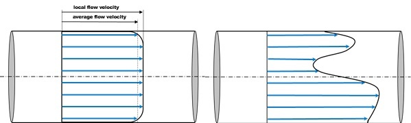
Flow measurement technology is based on an ideal, even and symmetrical flow profile. The flow velocity is measured at the center of the pipeline or duct, where it is the greatest. The measured value is converted to the average flow velocity in order to calculate the volumetric flow rate using the cross-sectional area. In practice, structural constraints often result in insufficient input and output sections, which leads to asymmetrical flow profiles. To still be able to perform an accurate volumetric flow measurement, the average flow velocity can be determined using a grid measurement. To do this, the measurement cross-section is divided into equal elements and the flow velocity is measured in each element. The sum of all values measured using the grid or tangential method, divided by the number of measuring points in the flow cross-section, results in the average flow velocity.

Recommended products

Vane wheel sensor ZS25

Product Product data sheet


Handheld unit flowtherm NT.2

ProductProduct data sheet

What is the purpose of grid measurement of fluid flow?

The exact average flow velocity is determined using grid measurements in flow cross-sections. The more measurements are taken per cross-section, the more accurate the result.

Process piping systems have several operating conditions of which each can be separately measured. This is important because the flow can change depending on the operating conditions. It also allows for better consideration of disturbances in the gas flow within the pipe or duct, regardless of whether the exhaust ducts are circular or rectangular. Grid measurements are the base for efficient and and safe processes even under initially challenging flow conditions.    

Who needs grid measurements?

Anyone who expects precise measurement results for their process control or analysis, but does not have the input or output sections required and can not or does not want to use flow straighteners, needs a grid measurement. It is a requirement for an accurate fixed measurement during operation. As a result, grid measurements are applied in many different industries and applications, like refineries and pipelines, chemical plants, power plants and exhaust gas cleaning systems.

This also applies to HVAC systems, such as those used to control building ventilation - for example in pharmaceutical or food processing facilities. As a measurement service provider, Höntzsch has been performing grid measurements for decades - even in explosive atmospheres.


What causes disruptions in the gas flow?

Fittings and changes in the cross-section within a pipeline or a tunnel disrupt the flow profile. Even a single pipe bend can cause asymmetries. Other sources of flow disturbance include for example valves, larger measurement devices and slide gates. All of these require grid measurements at the location where the sensor will later be permanently installed. 

Here's what a grid measurement looks like:

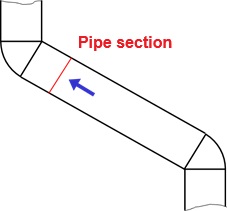
The exhaust air from a chemical process is discharged to the outside via a rectangular exhaust duct with the help of an axial fan. The fan is installed horizontally, the downstream piping includes several pipe bends and changes in the cross sections. This results in a highly disturbed flow profile. To determine the exact conditions and thus enable precise flow measurement in the duct, a grid measurement is required. Based on the measurement data obtained, the permanently installed sensor is then positioned, installed and calibrated.

How is a grid measurement performed?

In a rectangular exhaust duct, the segmentation for the grid measurement is performed using lines running parallel to the sides of the duct, so that the duct is divided into geometrically equal elements (see image below). The individual measuring points used in this method for rectangular exhaust ducts are then located at the center of each area. 

At the measuring point for portable measurement, additional holes must be drilled for the installation of the plant grid measuring points. The holes must be positioned so that the measurement points

a) are located within the segments of the grid measurement and
b) represent the flow cross-section

To keep the number of holes to a minimum, they will be drilled on the shorter side of the rectangle. 

Different operating stages

It's important to know the possible operating conditions. In this example the blower motor is driven by a freqency converter. Three different frequencies are programmed into the blower control system. Consequently, a separate measurement must be performed for each operating condition.

Performing grid measurement

Portable flow measurement is performed as a grid measurement using our vane wheel sensor ZS25 and a handheld unit. The probe is inserted into the prepared side openings of the exhaust duct and the flow is measured in each predefined measurement point along the cross-section. 

The recorded values are compiled and evaluated. The average flow velocity is calculated by dividing the sum of all individual values by the number of measuring points:

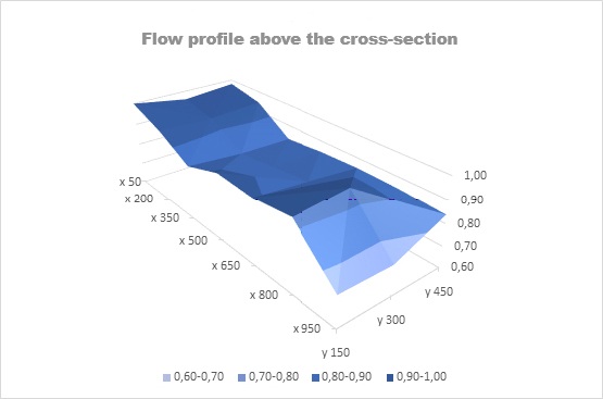
The flow profile of the rectangular exhaust duct under investigation is shown below on a normalized scale. As can be seen here, a highly uneven distribution develops.

Grid measurements in the flow cross-sections are performed for each operating point to obtain an accurate assessment of the measured flow velocity. 

To install the sensor at what is then considered a “representative” measuring point, a so-called profile factor is determined for the installation position of the fixed flow sensor. The average flow velocity can be calculated based on the local flow velocity. 

What are other grid measurement methods in ducts and pipelines?

For flow measurement in a round pipe, the measurement cross-section is divided into equal elements using the so called tangential method. In the tangential method the measuring points are located at the midpoint of two or more diameters, which serve as a measurement axis. The center of the pipe is deliberatly not taken into account here. 

In the centroidal line method for grid measurements in circular cross-sections, the circular duct cross-section is divided into equal circular rings, with the measurement location for the portable flow measurement positioned on the centerline of the circular ring. The measurement is evaluated by calculating the arithmetic average of the individually measured values.