Gas ejection blowers in natural gas pipelines
Measuring of flow rate at gas ejection blowers in natural gas pipelines
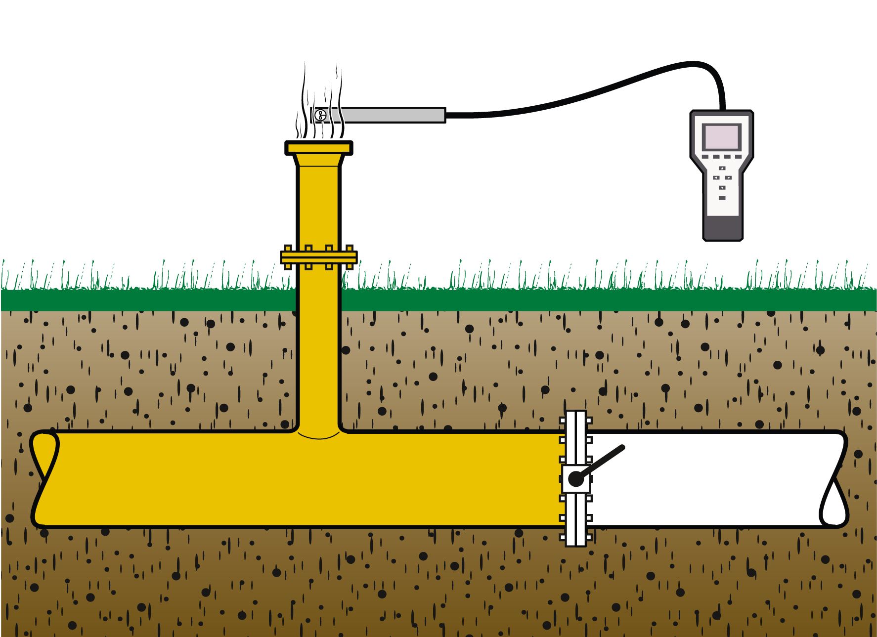
When building and maintaining natural gas pipelines they have to frequently be filled with natural gas and floated with air. The DVGW set certain rules for the process. The volume of the pipe section needs to be completely gassed or degassed. Flow rate is measured at the so called gas ejection blower, a pipe vertically attached to the grounding line. Velocities over 100 m/s are possible there.
A certain maximum speed must not be exceeded in the usually underground main pipe to avoid an intermixture of natural gas and air. To ensure said process the velocity is monitored through flow rate measurement.
Ball valves separate the pipe sections. To fill the pipe with gas one of the ball valves is slowly opened until the wanted flow rate or flow velocity is reached. Due to the natural gas, explosive gas mixtures can occur at the gas ejection blower often making the area surrounding it an ex-protection zone in which case only ex-devices with an according certification are allowed to be used.
The vane wheel sensor can be used for many velocities. It can be installed with extension rods and a direction indicator to ensure a certain distance at the gas outlet. Fixed installation with a probe guide piece is also possible.
Measured values such as flow velocity and flow rate can be stored and read in the handheld unit. The data can then be transferred to a computer for further data processing.
Impermeability tests on ball valves (analog DVGW G 411):
Ball valves have to be checked for their impermeability parallel to the filling of the gas pipes (analog technical data sheet DVGW G 411). The ball valve is closed. At the pressureless side the leackage flow rate is being measured and compared to the allowed limits. That way ball valves can be checked before installation and already installed ones can be checked for leakages. Our vortex sensor is perfectly suited for such applications since it delivers reliable values even in gas with deposits.
Our measuring system constisting of sensor and handheld unit is also able to monitor and determine other gas flows.
For informations about leakage measurement at large ball valves in gas pipelines, klick here.


